Back in the day, the billycart was the ultimate in kids’ fun – a couple of planks of wood, a few pram tyres you found in the kerbside clean-up and a bit of old rope was all it took to keep the whole neighbourhood busy for hours on end.
WATCH: Adam makes the ultimate billy cart using a wheelbarrow
This sensational street machine is a nod to more simple times. The modern cart has a few extra creature comforts and is a bit more up to date but that doesn’t mean it’s any less fun. Your whole street will be lining up to have a go in this hot rod!
Gather your supplies
- Chassis (2)1465 x 400 x 15mm plywood
- Uprights (6) 270 x 70 x 35mm pine
- Dashboard 400 x 70 x 35mm pine
- Steering support rail 330 x 70 x 35mm pine
- Body panels (2) 1800 x 305 x 3mm plywood
- Axle blocks (2) 750 x 70 x 35mm pine
- Seat back 590 x 320 x 15mm plywood offcut
- Front axle disc 140mm-dia. x 3mm plywood
- Steering cable wheels (2) 80mm-dia. x 15mm plywood
- Inner steering cable wheel 74mm-dia. x 3mm plywood
- Steering cable 3mm x 1600mm galv wire cable
- Steering column stoppers (2) 48mm-dia. x 15mm plywood
- Steering column 25mm x 600mm dowel
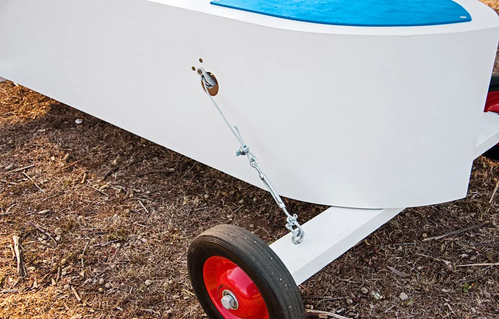
- Steering pulley blocks (2) 70 x 35 x 75mm pine
- Brake rails (2) 42 x 19 x 300mm Tasmanian oak
- Brake handle 42 x 19 x 350mm Tasmanian oak
- Brake block 70 x 35 x 70mm pine
- Steering wheel 205 x 110 x 15mm ply
You’ll also need
Circular saw; jigsaw; belt sander; power planer; 25mm soft sheet nails; Spakfilla; 25mm spade bit; Dulux 1 Step Primer, Sealer & Undercoat; Dulux Aquanamel in Vivid White plus another colour of your choice; 40 x 60 x 50mm angle bracket (4); 150mm M12 galvanised coach screws and 2 washers (4); 75mm M10 galvanised cup head bolt, 2 nuts and washer; 86, 54 and 44mm hole saws; 20mm awning pully (2); 50mm eyebolt (2); ¼in Nyloc nuts (2); 5mm D shackles (2); 5mm eye and eye turnbuckles (2); 75mm M8 hex head bolt, nuts and washers
Notes
- All joints are glued and screwed unless otherwise indicated.
- All screws are countersunk.
- Check all components against actual unit as it is being built before cutting to size.
- All metal hardware is galvanised.
Here’s how
Step 1
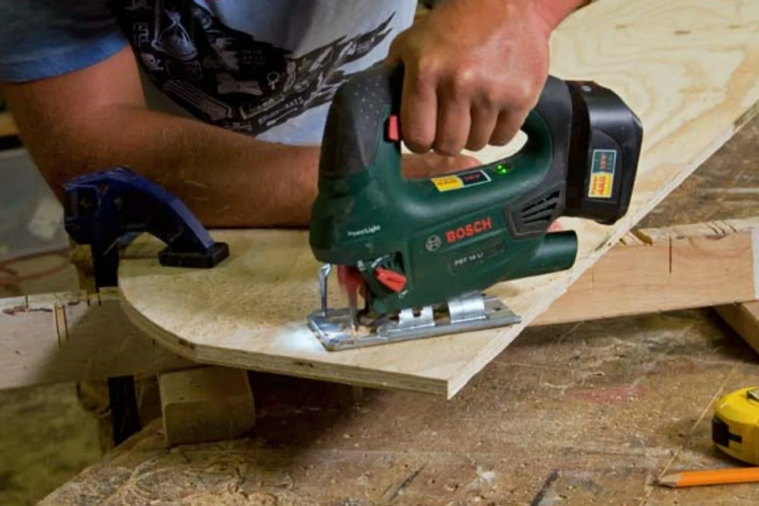
Cut chassis pieces (A) from sheets of ply by clamping a straightedge to 1 sheet of ply as a guide for base of saw and making sure blade of saw is on cutting line. Mark centre of short sides and, using this as a starting point, draw gentle freehand curves at each end that finishes 290mm down the long sides. The point at front and back should be fairly blunt at 125°-130°. Cut curves with jigsaw. Place this piece on second sheet of ply, then trace curve and cut.
Step 2
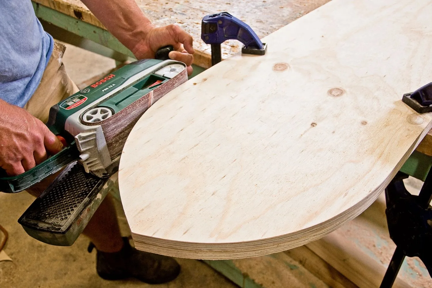
Clamp chassis pieces together and use belt sander to smooth edges.
Step 3
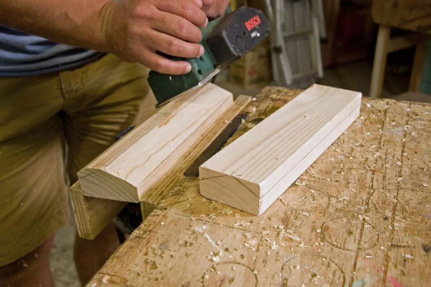
Place an upright (B) on chassis so centre of wide face is flush with point of the curve. Trace point and curve on both ends of upright. Draw a line down side to join marks on each end. Plane upright on an angle until you reach the lines.
Step 4
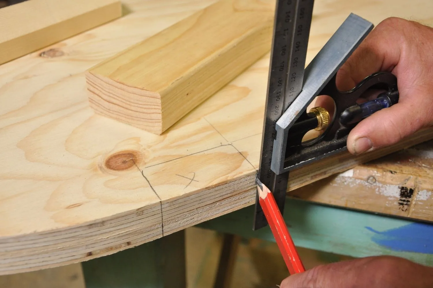
Place these uprights back on ends. The other uprights sit on the long side of chassis, 290mm from the ends. Trace their position on chassis. Use a combination square to mark position of uprights down the edge to second chassis piece. Drill clearance holes through chassis pieces for the uprights.
Step 5
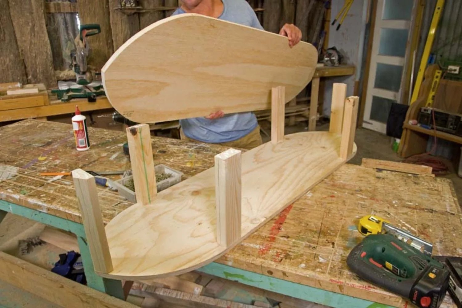
Separate chassis pieces, place uprights back in position and screw through 1 chassis piece into them. Place second chassis piece on top, making sure marks on the side match with uprights. Screw chassis to uprights.
Step 6
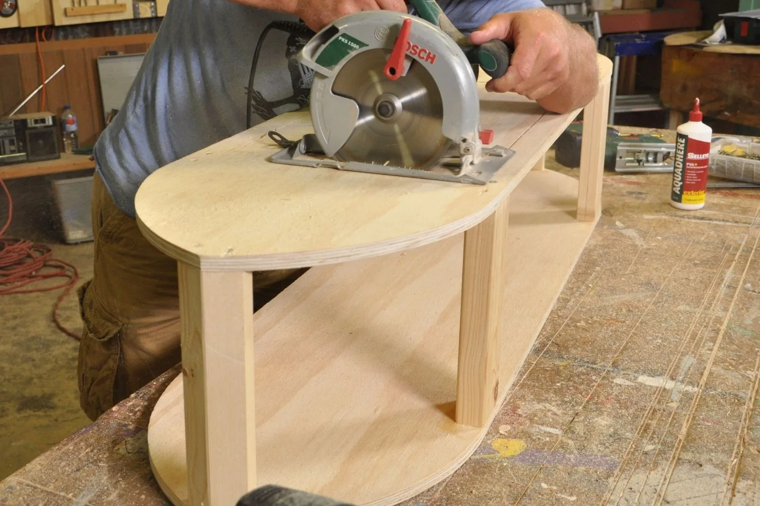
Mark out position of cockpit and engine bay on top of chassis. Cut-out for cockpit is 325 x 595mm, centred on the chassis. It starts 360mm from 1 end (which will now be the rear). Cut-out for engine bay follows line of chassis, 75mm in from side. It finishes 410mm from front of chassis. Cut the straight lines with a circular saw. Pull back guard of saw and plunge blade down on the waste side of the line. Cut on lines as cut-out will be used for seat back later on. Finish corners and curved shapes with jigsaw. Sand all cut edges smooth.
Step 7
Attach dashboard (C) flush with front of cockpit. Screw steering support rail (D) between front uprights so it sits 45mm down from top of chassis and is at a slight angle to be right angles to steering column (see Step 15).
Step 8
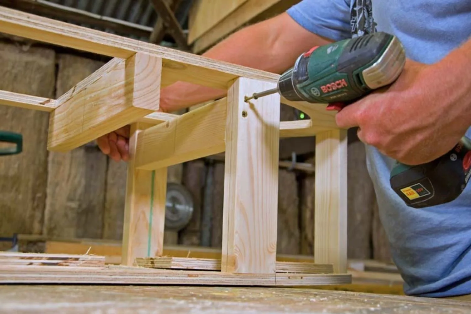
Apply glue and lay 1 body panel (E) on side of chassis so it overhangs at top and bottom. Nail it at 60mm centres along straight part of chassis. Bend ply around curve, using a clamp to pull it into shape and nail. Mark front of chassis down the body panel and cut off excess with saw set to depth of 5mm. Repeat with other side, using your bench to clamp curve down. Sand cut ends so they are flush with each other.
Step 9
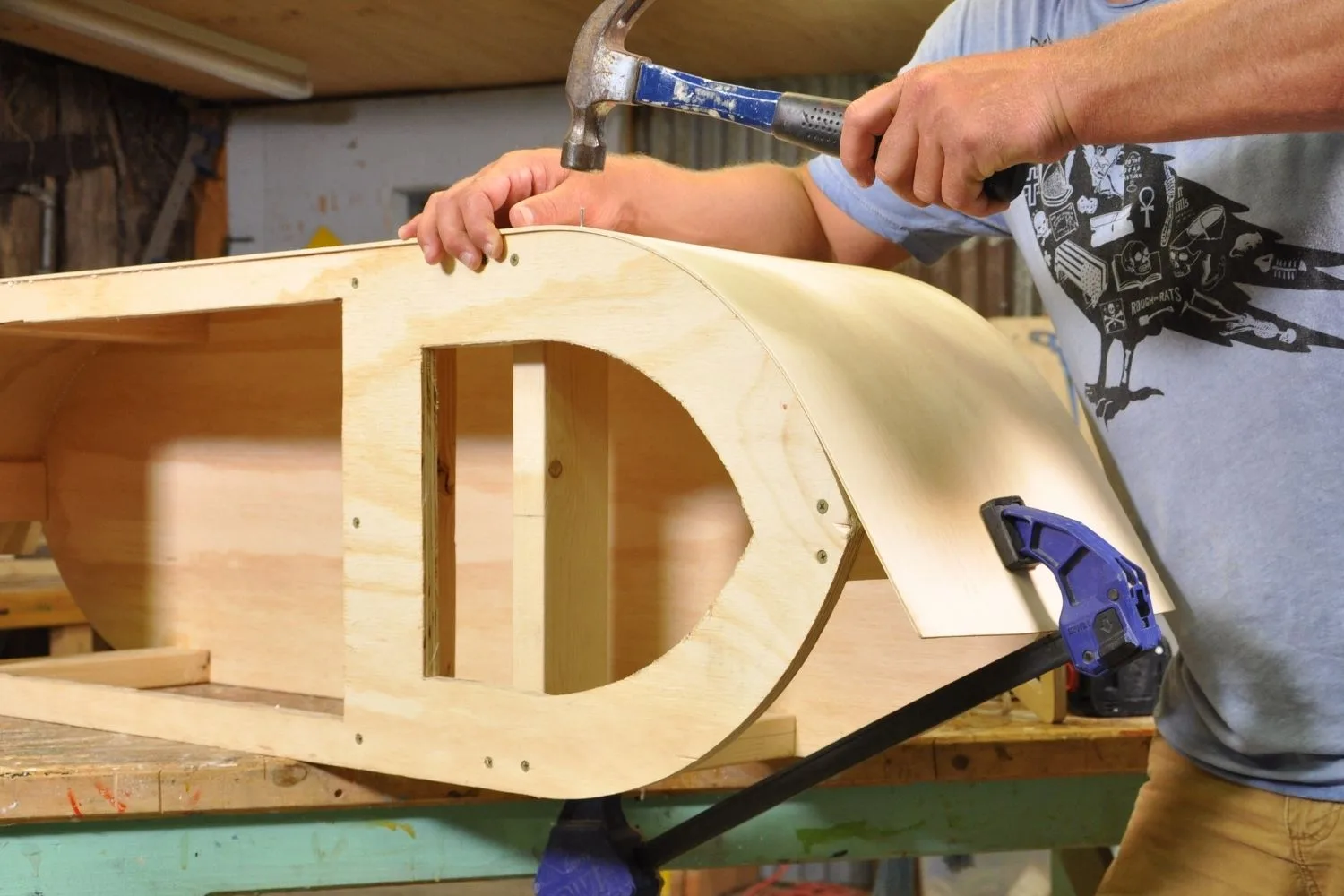
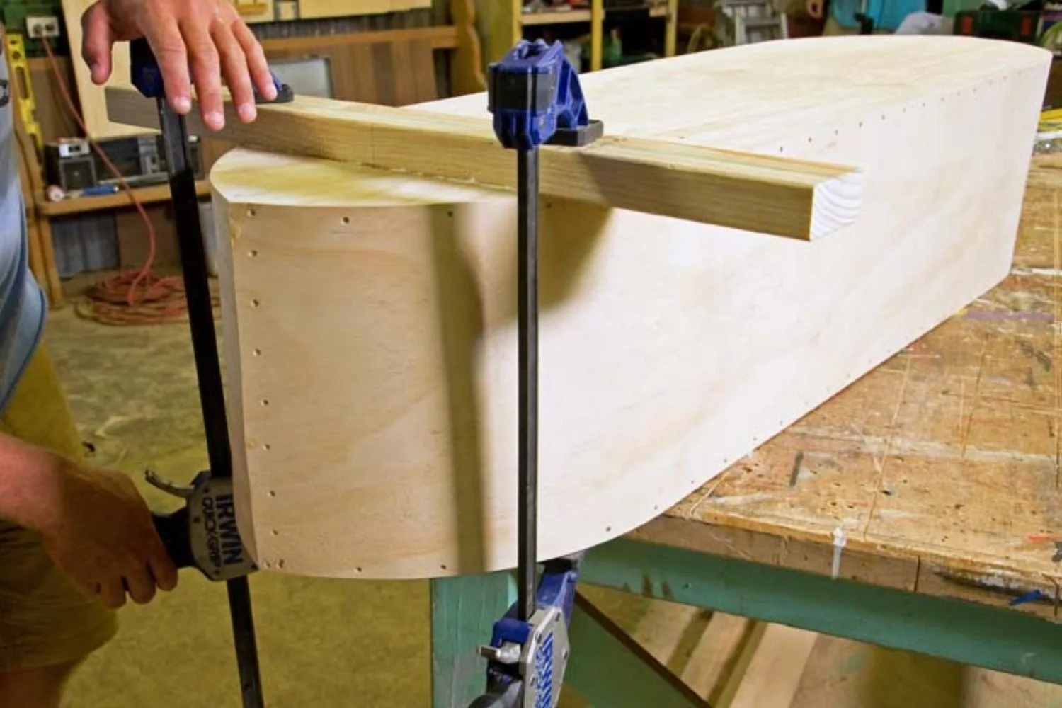
Turn chassis over and mark centre line down underside. Clamp axle block (F) to chassis so centre is 185mm from rear end and middle of block is aligned with centre line. Turn chassis back over, and screw through chassis into axle block.
Step 10
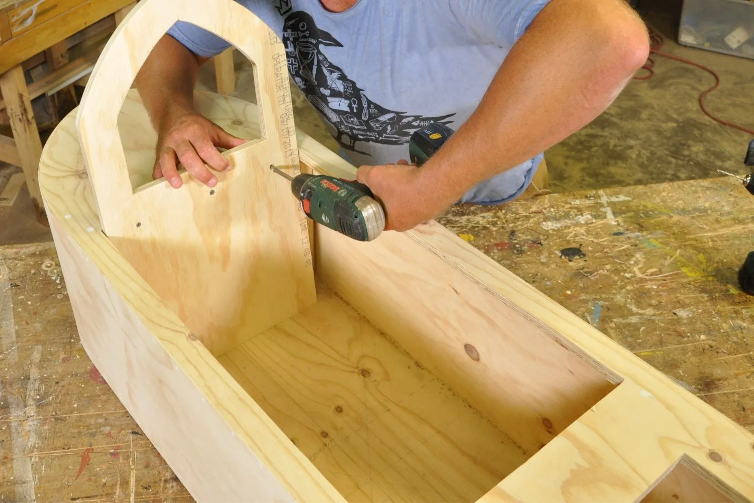
To make seat back (G), use cockpit cut-out offcut. Curve 1 end with it finishing 150mm down the long side. Mark a line 50mm in from sides, finishing 270mm from point of curve, and square it off. Cut out shape and sand edges smooth. Place in back of cockpit, leaning it slightly so bottom is 55mm from the vertical. Screw through seat back into top of chassis and up through chassis into bottom of seat back.
Step 11
Sand body panels where they overhang chassis until flush. Punch and fill all nail holes and gaps. Sand smooth. Undercoat cart and axle blocks. When dry, apply topcoats.
Step 12
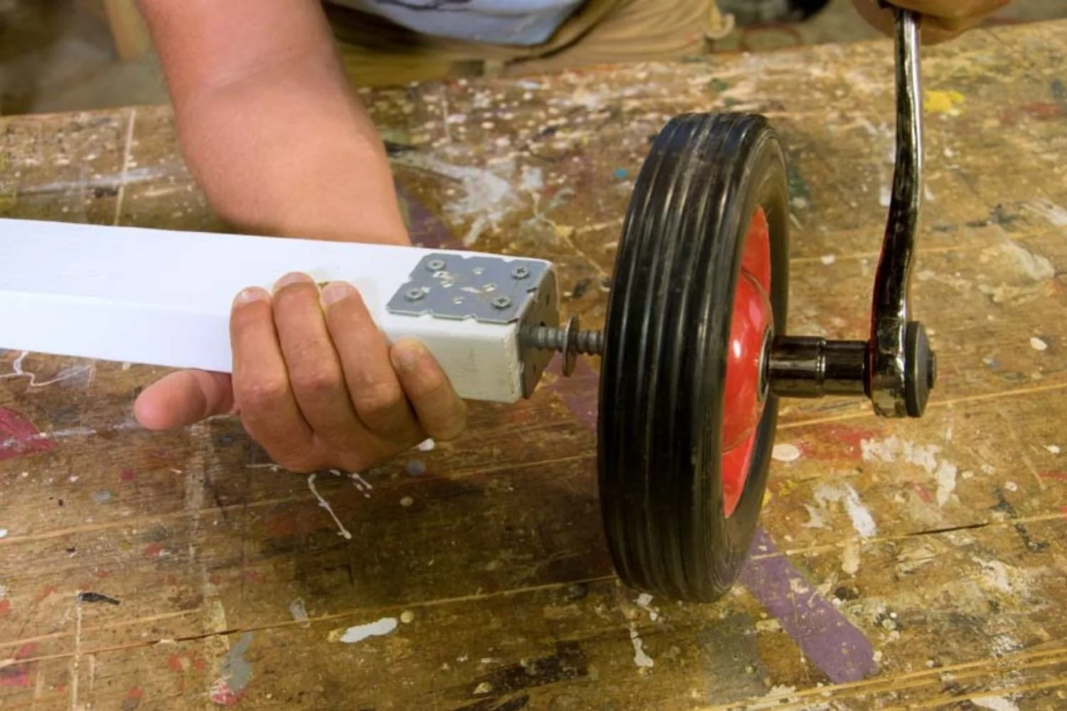
Drill a 12mm hole in centre of short leg of angle bracket. Screw this onto axle block so short leg is centred on end of block and long leg is on underside. Drill a 9mm hole into end of axle block through angle bracket. Slide a washer and wheel over coach screw followed by another washer and put in hole. Tighten coach screw, leaving it a few millimetres from axle block so wheel can spin freely. Repeat for all wheels.
Step 13
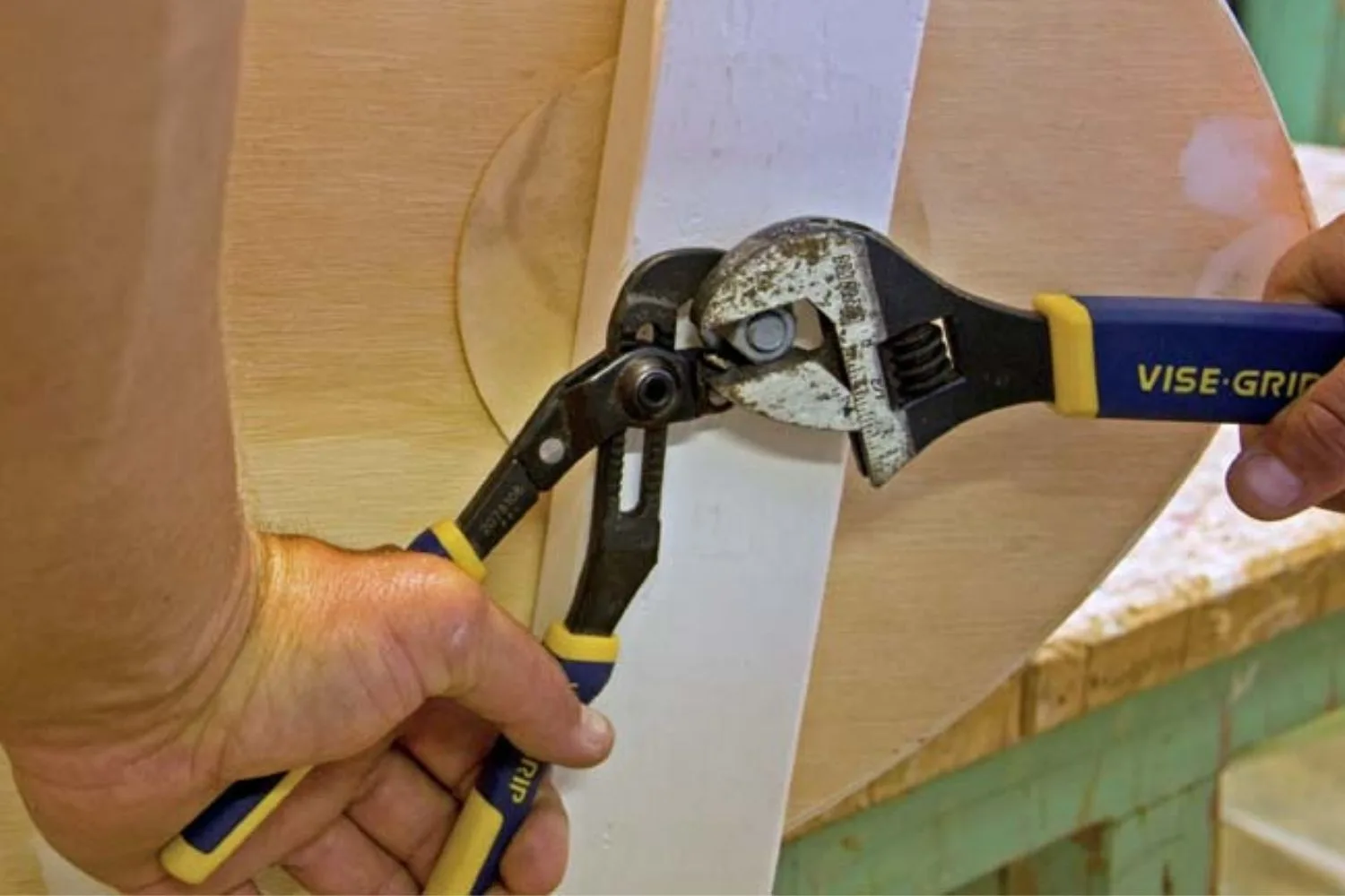
Drill 10mm hole in centre of underside of chassis 120mm from front, and 1 in centre and middle of front axle block. Push M10 cup head bolt through from inside the cart. Place front axle disc (H) over bolt, followed by front axle block, washer and nut. Finger tighten nut. Wind on another nut and, while holding the first with multigrips, tighten second nut. This is a locking nut that will ensure it does not come loose.
Step 14
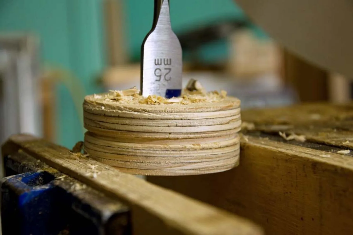
Using an 86mm hole saw, cut steering cable wheels (I, J). Sand inner wheel until it is 6mm smaller than outer wheels. Centre inner wheel between outer wheels and screw together. Drill through centre with 25mm spade bit. Place steering cable (K) in groove with equal lengths overhanging, then hammer in a couple of galvanised staples to secure. Punch staples down to secure cable. Using 54mm hole saw, cut steering column stoppers (L). Drill a 25mm hole in centre.
Step 15
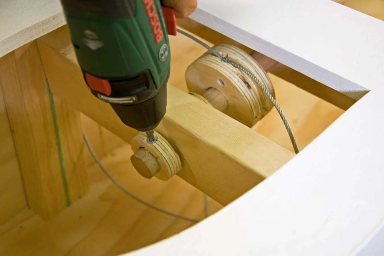
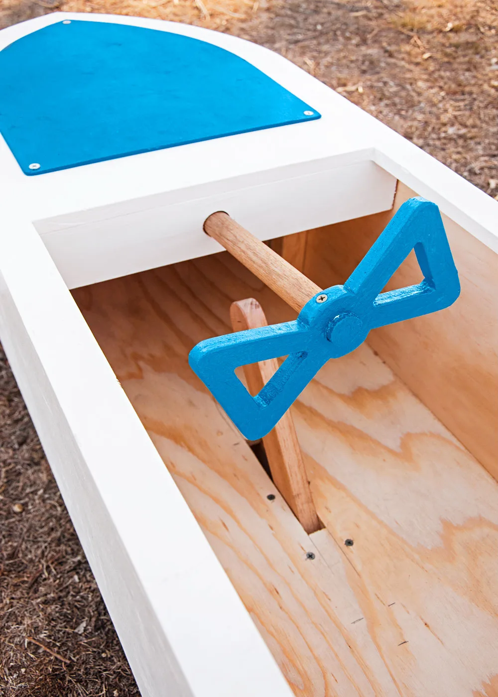
Drill a 25mm hole through dashboard. Angle drill slightly so it lines up with centre of angled steering support rail. With the spade bit in an drill extension bit, drill through steering support rail. Push steering column (M)through dashboard, then steering cable wheel and a steering column stopper. Continue through steering support rail, then slip another stopper on end. You may have to sand dowel slightly so it easily slides through holes. Screw steering cable wheel and stoppers to steering column.
Step 16
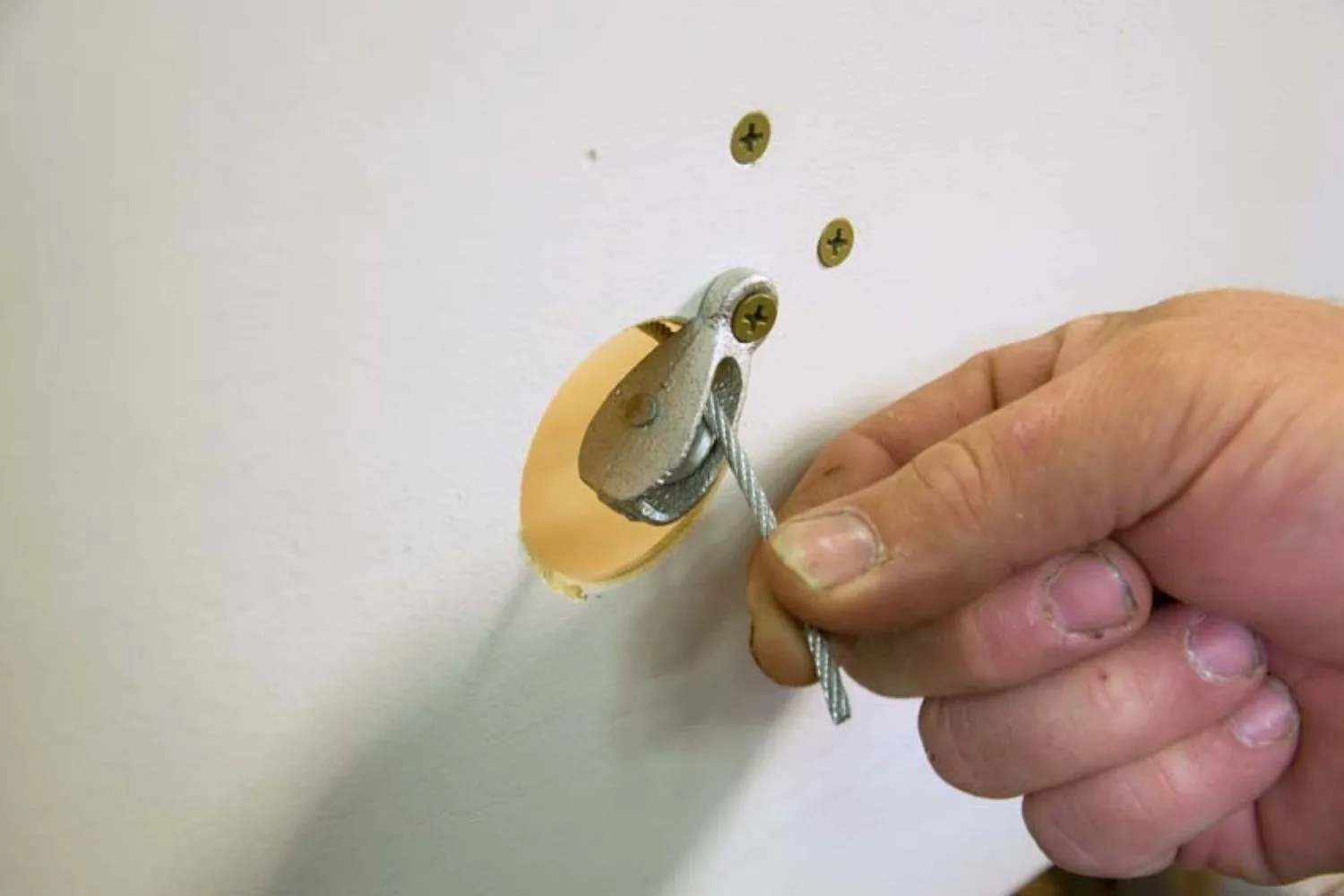
Make a mark, 125mm from top of body in line with steering cable wheel. Using 44mm hole saw, drill hole centred on mark. Attach steering pulley blocks (N) to inside of body, screwing through sides into the block. Then screw pulley to outside of body at a 45° angle so screws go through sides into pulley block. Pull cable around steering cable wheel and through pulley on opposite side of cart.
Step 17
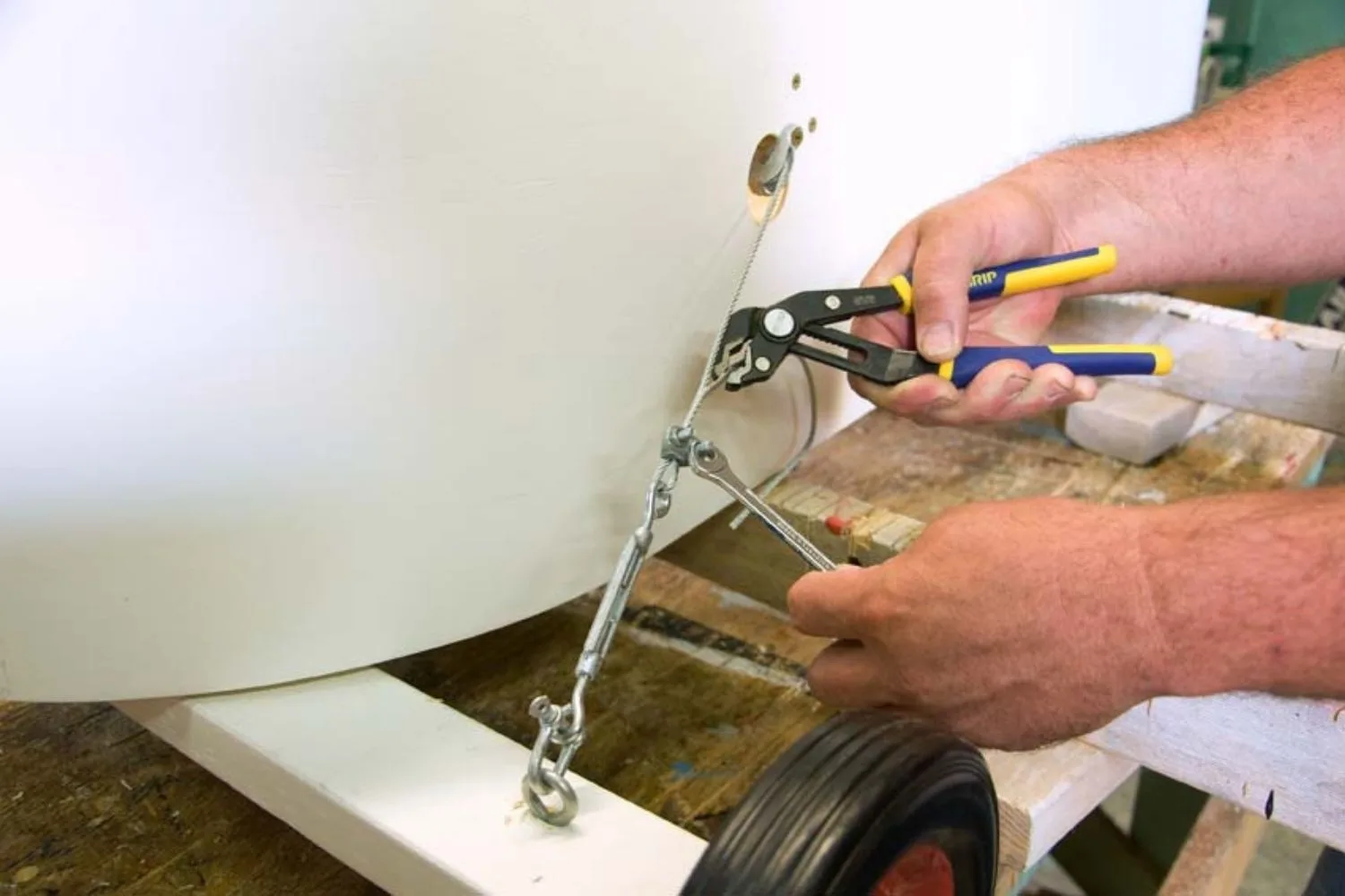
Drill holes in centre of front axle block, 100mm from each end. Drop eyebolts through holes and tighten with Nyloc nuts. Attach turnbuckle to eyebolt with D shackle. Wind out eyes on turnbuckle. Place clamp on steering column so it cannot spin and thread wire through other end of turnbuckle. Pull wire tight and hold with wire rope grips. Snip off excess wire. Further tighten wire by winding in turnbuckles.
Step 18
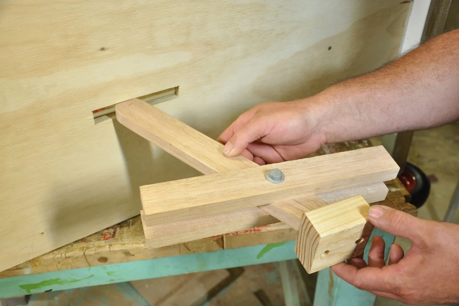
Cut a 30° angle on bottom of brake handle (P). Use jigsaw to round off other end and sand smooth. Screw (but don’t glue) brake block (Q) to handle, counterboring screws to half the depth of block. Drill 8mm hole in centre of handle, 80mm up from long end of angled cut. Drill same hole in middle of brake rails (O). Attach brake rails to either side of handle with 8mm bolt. Tighten with locking nut so handle can still move but is not loose. Starting 600mm from the front, cut a 135 x 20mm slot in centre of underside of cart. Place brake assembly through slot. Screw through chassis into brake rails so they are 565mm from front of cart.
Step 19
Use grid template (see page 2) to mark out steering wheel (R) and cut with jigsaw. Use 25mm spade bit for hole in centre. Cut bonnet (S) to shape, making curve at front finish 175mm down from point. Undercoat both pieces and finish in acrylic. Cut steering column to length to suit driver and screw steering wheel on. Screw bonnet to cart. And you’re off!
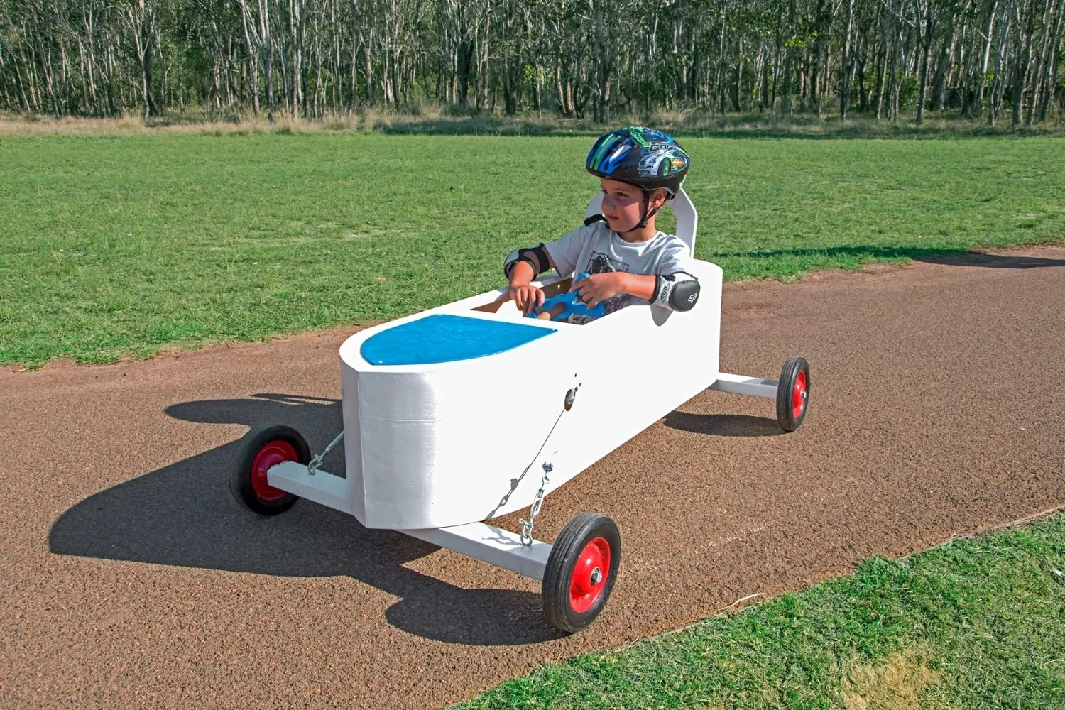
We have put the step-by-step instructions for this billycart on a pattern sheet so it’s easy for you to put together. Click here for the pattern sheet.
